A sequence diagram can map a scenarios described by a use case in step by step detail to define how objects collaborate to achieve your application’s goals
OR
UML sequence diagrams are used to show how objects interact in a given situation. An important characteristic of a sequence diagram is that time passes from top to bottom : the interaction starts near the top of the diagram and ends at the bottom
A lifeline in a sequence diagram represents an object and shows all its points of interaction with other objects in events that are important to it. Lifelines start at the top of a sequence diagram and descend vertically to indicate the passage of time. Interactions between objects – messages and replies – are drawn as horizontal direction arrows connecting lifelines. In addition, boxes known as combine fragments are drawn around sets of arrows to mark alternative actions, loops, and other control structures.
sequence diagram toolbar for quick access to specialized UML elements including lifelines, combine fragments, gates, message call and reply arrows, message arrows that create new lifelines or destroy existing objects, notes, and more.
all UML diagrams, comments are shown in a rectangle with a folded-over corner :
Objects as well as classes can be targets on a sequence diagram, which means that messages can be sent to them. A target is displayed as a rectangle with some text in it. Below the target, its lifeline extends for as long as the target exists. The lifeline is displayed as a vertical dashed line.
Object
The basic notation for an object is
As with any UML-element, you can add a stereotype to a target. Some often used stereotypes for objects are «actor», «boundary», «control», «entity» and «database». They can be displayed with icons as well :
Messages
When a target sends a message to another target, it is shown as an arrow between their lifelines. The arrow originates at the sender and ends at the receiver. Near the arrow, the name and parameters of the message are shown.
Synchronous message
A synchronous message is used when the sender waits until the receiver has finished processing the message, only then does the caller continue (i.e. a blocking call). Most method calls in object-oriented programming languages are synchronous. A closed and filled arrowhead signifies that the message is sent synchronously.
The white rectangles on a lifeline are called activations and indicate that an object is responding to a message. It starts when the message is received and ends when the object is done handling the message.
When a messages are used to represent method calls, each activation corresponds to the period during which an activation record for its call is present on the call stack.
If you want to show that the receiver has finished processing the message and returns control to the sender, draw a dashed arrow from receiver to sender. Optionally, a value that the receiver returns to the sender can be placed near the return arrow.
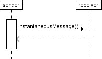
Instantaneous message
Messages are often considered to be instantaneous, i.e. the time it takes to arrive at the receiver is negligible. For example, an in-process method call. Such messages are drawn as a horizontal arrow
Message to self
A message that an object sends itself can be shown as follows :

Keep in mind that the purpose of a sequence diagram is to show the interaction between objects, so think twice about every self message you put on a diagram.
Creation and destruction
Targets that exist at the start of an interaction are placed at the top of the diagram. Any targets that are created during the interaction are placed further down the diagram, at their time of creation.

A target's lifeline extends as long as the target exists. If the target is destroyed during the interaction, the lifeline ends at that point in time with a big cross
Conditional interaction
A message can include a guard, which signifies that the message is only sent if a certain condition is met. The guard is simply that condition between brackets.

If you want to show that several messages are conditionally sent under the same guard, you'll have to use an 'opt' combined fragment. The combined fragment is shown as a large rectangle with an 'opt' operator plus a guard, and contains all the conditional messages under that guard.

A guarded message or 'opt' combined fragment is somewhat similar to the if-construct in a programming language.
If you want to show several alternative interactions, use an 'alt' combined fragment. The combined fragment contains an operand for each alternative. Each alternative has a guard and contains the interaction that occurs when the condition for that guard is met.

At most one of the operands can occur. An 'alt' combined fragment is similar to nested if-then-else and switch/case constructs in programming languages.
Repeated interaction
When a message is prefixed with an asterisk (the '*'-symbol), it means that the message is sent repeatedly. A guard indicates the condition that determines whether or not the message should be sent (again). As long as the condition holds, the message is repeated.

The above interaction of repeatedly sending the same message to the same object is not very useful, unless you need to document some kind of polling scenario.
A more common use of repetition is sending the same message to different elements in a collection. In such a scenario, the receiver of the repeated message is a multiobject and the guard indicates the condition that controls the repetition.

This corresponds to an iteration over the elements in the collection, where each element receives the message. For each element, the condition is evaluated before the message is sent. Usually though, the condition is used as a filter that selects elements from the collection (e.g. 'all', 'adults', 'new customers' as filters for a collection of Person objects). Only elements selected by the filter will receive the message.
If you want to show that multiple messages are sent in the same iteration, a 'loop' combined fragment can be used. The operator of the combined fragment is 'loop' and the guard represents the condition to control the repetition.

Again, if the receiver of a repeated message is a collection, the condition is generally used to specify a filter for the elements.
For example, to show that the bounds of a drawing are based on those of its visible figures we could draw the following sequence diagram :

Several things are worth noting in this example
- a local variable 'r' was introduced to clarify that it is the result of getBounds that is added.
- naming the resulting Rectangle 'bounds' avoids the introduction of an extra local variable.
- the loop condition is used as a filter on the elements of the figures collection.