Sunday, 28 October 2012
Thursday, 25 October 2012
DOS Commands With Examples
The following is a list of useful DOS commands, with explanations. They are useful on older DOS systems and in the command-line interface on modern Windows systems. To access the command-line interface:
- Windows 7 or Vista: Click
Start, typecmd, and then pressEnter.Certain commands may require administrative access on Windows 7 or Vista. To launch the command line interface in administrative mode, clickStart, typecmd, and then right-click thecmdorcmd.exesearch result and chooseRun as Administrator. - Windows XP: Click
Start, thenRun. Typecmd, and then pressEnter.
file.ext, file1, file2), file extensions (.ext), directories (e.g., diry,diry1, diry2), commands (e.g.,command), and drive letters (e.g., a:,b:, c:) are given, substitute the name of your own file, directory, command, or drive letter. Since DOS is not case-sensitive, you can type these commands in either upper- or lowercase.help | List commands (only in DOS versions 5 or later). |
help command | See help for the DOScommand. |
command /? | List switches for the DOScommand. |
path=c:\windows ; c:\dos | Specify in which directories DOS searches for commands or programs. |
prompt $p$g | Make the DOS prompt display the current directory. |
dir | List files in the current directory in one column. |
dir /w | List files in five columns. |
dir /p | List files one page at a time. |
dir *.ext | List all files with an.ext extension. |
dir z???.ext | List files with .extextensions that have four letters and start with z (where z is a character of your choice). |
dir file.ext /s | Search for thefile.ext in the current directory and all subdirectories under the current directory; most useful if the current directory is the root (i.e., C:\ ). |
type file.ext | View the contents of the text filefile.ext. |
edit file.ext | Use the DOS editor to edit the file file.ext. |
a: | Change to the a: drive. |
md c:\diry | Make a new subdirectory nameddiry in the c:\ directory. |
cd c:\diry | Change to subdirectorydiry. |
rd c:\diry | Remove the existing subdirectory named diry. |
del file.ext | Delete a file namedfile.ext. |
ren file1 file2 | Rename file file1to file2. |
copy file1 file2 | Copy file file1to file2. |
verify on | Turn on verification of copy commands. |
verify off | Turn off verification of copy commands. |
xcopy diry1 diry2 /s | Copy all files and subdirectories in directory diry1 to diry2. |
xcopy diry1 diry2 /p | Ask for confirmation of each file before copying it from diry1 todiry2. |
diskcopy a: b: | Duplicate a disk using two floppy drives. |
diskcopy a: a: | Duplicate a disk using the same floppy drive. |
format a: | Format a disk in drivea: . |
format a: /s | Format a bootable disk (include system files). |
backup c:\diry\*.ext a: | Back up all files with the extension .ext in c:\diry\ to drivea: . |
backup c:\ a: /s | Back up the entirec: drive to drive a: . |
restore a:\ c:\diry\*.ext | Restore backed-up files with the extension .ext in drive a: to the c:\diry\ directory. |
restore a: c:\ /s | Restore backed-up files and subdirectories from drive a: to c:\ . |
ver | Check the version of DOS. |
time | Check or correct the system time. |
date | Check or correct the system date. |
cls | Clear the screen. |
scandisk | Scan and check drive c:for errors. ScanDisk replaces chkdsk (see below) on DOS version 6.0 and above (including Windows 95). |
chkdsk | Check disk and memory usage of the current disk. |
chkdsk /f | Fix errors reported bychkdsk. |
chkdsk file.ext | Check a particular file. |
chkdsk a: | Check a particular drive (in this case, a floppy in the a: drive). |
mem | Check memory usage. |
Monday, 15 October 2012

Sunday, 14 October 2012
What is Sequence Diagram in UML
A sequence diagram can map a scenarios described by a use case in step by step detail to define how objects collaborate to achieve your application’s goals
OR
UML sequence diagrams are used to show how objects interact in a given situation. An important characteristic of a sequence diagram is that time passes from top to bottom : the interaction starts near the top of the diagram and ends at the bottom
A lifeline in a sequence diagram represents an object and shows all its points of interaction with other objects in events that are important to it. Lifelines start at the top of a sequence diagram and descend vertically to indicate the passage of time. Interactions between objects – messages and replies – are drawn as horizontal direction arrows connecting lifelines. In addition, boxes known as combine fragments are drawn around sets of arrows to mark alternative actions, loops, and other control structures.
sequence diagram toolbar for quick access to specialized UML elements including lifelines, combine fragments, gates, message call and reply arrows, message arrows that create new lifelines or destroy existing objects, notes, and more.

 Objects as well as classes can be targets on a sequence diagram, which means that messages can be sent to them. A target is displayed as a rectangle with some text in it. Below the target, its lifeline extends for as long as the target exists. The lifeline is displayed as a vertical dashed line.
 As with any UML-element, you can add a stereotype to a target. Some often used stereotypes for objects are «actor», «boundary», «control», «entity» and «database». They can be displayed with icons as well :

 The white rectangles on a lifeline are called activations and indicate that an object is responding to a message. It starts when the message is received and ends when the object is done handling the message.
When a messages are used to represent method calls, each activation corresponds to the period during which an activation record for its call is present on the call stack.
If you want to show that the receiver has finished processing the message and returns control to the sender, draw a dashed arrow from receiver to sender. Optionally, a value that the receiver returns to the sender can be placed near the return arrow.


Keep in mind that the purpose of a sequence diagram is to show the interaction between objects, so think twice about every self message you put on a diagram.

A target's lifeline extends as long as the target exists. If the target is destroyed during the interaction, the lifeline ends at that point in time with a big cross
Conditional interaction
A message can include a guard, which signifies that the message is only sent if a certain condition is met. The guard is simply that condition between brackets.

If you want to show that several messages are conditionally sent under the same guard, you'll have to use an 'opt' combined fragment. The combined fragment is shown as a large rectangle with an 'opt' operator plus a guard, and contains all the conditional messages under that guard.

A guarded message or 'opt' combined fragment is somewhat similar to the if-construct in a programming language.
If you want to show several alternative interactions, use an 'alt' combined fragment. The combined fragment contains an operand for each alternative. Each alternative has a guard and contains the interaction that occurs when the condition for that guard is met.

At most one of the operands can occur. An 'alt' combined fragment is similar to nested if-then-else and switch/case constructs in programming languages.

The above interaction of repeatedly sending the same message to the same object is not very useful, unless you need to document some kind of polling scenario.
A more common use of repetition is sending the same message to different elements in a collection. In such a scenario, the receiver of the repeated message is a multiobject and the guard indicates the condition that controls the repetition.

This corresponds to an iteration over the elements in the collection, where each element receives the message. For each element, the condition is evaluated before the message is sent. Usually though, the condition is used as a filter that selects elements from the collection (e.g. 'all', 'adults', 'new customers' as filters for a collection of Person objects). Only elements selected by the filter will receive the message.
If you want to show that multiple messages are sent in the same iteration, a 'loop' combined fragment can be used. The operator of the combined fragment is 'loop' and the guard represents the condition to control the repetition.

Again, if the receiver of a repeated message is a collection, the condition is generally used to specify a filter for the elements.
For example, to show that the bounds of a drawing are based on those of its visible figures we could draw the following sequence diagram :

Several things are worth noting in this example
OR
UML sequence diagrams are used to show how objects interact in a given situation. An important characteristic of a sequence diagram is that time passes from top to bottom : the interaction starts near the top of the diagram and ends at the bottom
A lifeline in a sequence diagram represents an object and shows all its points of interaction with other objects in events that are important to it. Lifelines start at the top of a sequence diagram and descend vertically to indicate the passage of time. Interactions between objects – messages and replies – are drawn as horizontal direction arrows connecting lifelines. In addition, boxes known as combine fragments are drawn around sets of arrows to mark alternative actions, loops, and other control structures.
sequence diagram toolbar for quick access to specialized UML elements including lifelines, combine fragments, gates, message call and reply arrows, message arrows that create new lifelines or destroy existing objects, notes, and more.

all UML diagrams, comments are shown in a rectangle with a folded-over corner :
Object
The basic notation for an object is
Messages
When a target sends a message to another target, it is shown as an arrow between their lifelines. The arrow originates at the sender and ends at the receiver. Near the arrow, the name and parameters of the message are shown.Synchronous message
A synchronous message is used when the sender waits until the receiver has finished processing the message, only then does the caller continue (i.e. a blocking call). Most method calls in object-oriented programming languages are synchronous. A closed and filled arrowhead signifies that the message is sent synchronously.
When a messages are used to represent method calls, each activation corresponds to the period during which an activation record for its call is present on the call stack.
If you want to show that the receiver has finished processing the message and returns control to the sender, draw a dashed arrow from receiver to sender. Optionally, a value that the receiver returns to the sender can be placed near the return arrow.
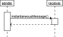
Instantaneous message
Messages are often considered to be instantaneous, i.e. the time it takes to arrive at the receiver is negligible. For example, an in-process method call. Such messages are drawn as a horizontal arrowMessage to self
A message that an object sends itself can be shown as follows : Keep in mind that the purpose of a sequence diagram is to show the interaction between objects, so think twice about every self message you put on a diagram.
Creation and destruction
Targets that exist at the start of an interaction are placed at the top of the diagram. Any targets that are created during the interaction are placed further down the diagram, at their time of creation.A target's lifeline extends as long as the target exists. If the target is destroyed during the interaction, the lifeline ends at that point in time with a big cross
Conditional interaction
A message can include a guard, which signifies that the message is only sent if a certain condition is met. The guard is simply that condition between brackets.
If you want to show that several messages are conditionally sent under the same guard, you'll have to use an 'opt' combined fragment. The combined fragment is shown as a large rectangle with an 'opt' operator plus a guard, and contains all the conditional messages under that guard.
A guarded message or 'opt' combined fragment is somewhat similar to the if-construct in a programming language.
If you want to show several alternative interactions, use an 'alt' combined fragment. The combined fragment contains an operand for each alternative. Each alternative has a guard and contains the interaction that occurs when the condition for that guard is met.
At most one of the operands can occur. An 'alt' combined fragment is similar to nested if-then-else and switch/case constructs in programming languages.
Repeated interaction
When a message is prefixed with an asterisk (the '*'-symbol), it means that the message is sent repeatedly. A guard indicates the condition that determines whether or not the message should be sent (again). As long as the condition holds, the message is repeated.The above interaction of repeatedly sending the same message to the same object is not very useful, unless you need to document some kind of polling scenario.
A more common use of repetition is sending the same message to different elements in a collection. In such a scenario, the receiver of the repeated message is a multiobject and the guard indicates the condition that controls the repetition.
This corresponds to an iteration over the elements in the collection, where each element receives the message. For each element, the condition is evaluated before the message is sent. Usually though, the condition is used as a filter that selects elements from the collection (e.g. 'all', 'adults', 'new customers' as filters for a collection of Person objects). Only elements selected by the filter will receive the message.
If you want to show that multiple messages are sent in the same iteration, a 'loop' combined fragment can be used. The operator of the combined fragment is 'loop' and the guard represents the condition to control the repetition.
Again, if the receiver of a repeated message is a collection, the condition is generally used to specify a filter for the elements.
For example, to show that the bounds of a drawing are based on those of its visible figures we could draw the following sequence diagram :
Several things are worth noting in this example
- a local variable 'r' was introduced to clarify that it is the result of getBounds that is added.
- naming the resulting Rectangle 'bounds' avoids the introduction of an extra local variable.
- the loop condition is used as a filter on the elements of the figures collection.
Tuesday, 2 October 2012
Learning Adobe Photoshop CS3
Click here to Learn and Download it....
http://www.scribd.com/doc/18082368/Learning-Adobe-Photoshop-CS3#download
http://www.scribd.com/doc/18082368/Learning-Adobe-Photoshop-CS3#download
What Is UML.??

What is UML?
UML is an acronym for Unified Modeling Language. UML is widely accepted as the de facto standard description language for the specification and design of object-oriented software systems. UML is a family of “languages”, or diagram types, that attempt to bring together the “best in breed” software specification techniques for describing software systems. Users and practicioners of UML can choose which members of the family are the most suitable for their application domain.
Personally, I have become associated with UML through my years and years of specifying software products. Several of the UML diagram types that I will discuss below are among my primary tools for communicating application and system requirements and software designs to programmers.
I do not advocate, nor do I personally practice, an over-attachment to UML. Like many of these project management and requirements management techniques, there is a time and a place for the proper introduction of these types of UML artifacts into the software development process. Programmers may be unfamiliar with the UML diagram types and symbology, and so if you are a business analyst, project, program or product manager, and you are using these types of project deliverables with a new staff of engineers, be prepared to explain the UML diagram type you are using, keep the introductions down to one or two different new UML “Languages”, or diagram types, at a time.
I also recommend that if you insert UML diagrams into your functional specification documents, and I recommend that if you have invested the time to properly prepare UML diagrams that you do leverage them into your spec docs, make sure that you include an explanatory prose component into your accompanying functional specification document’s text.
There are nine different types of UML languages, or diagram types:
1. Use Case.
2. Sequence.
3. Collaboration.
4. Statechart.
5. Activity.
6. Class.
7. Object.
8. Component.
9. Deployment.
Five of these diagram types render behavioral views, the use case, sequence, collaboration, statechart and activity diagrams, while the remaining four diagram types are concerned with architectural or static aspects of the software design.
How does UML help in specifying a software design?
UML is a graphical language that is based on the premise that any software system can be described in terms of interacting business entities and that various aspects of these entities and their interactions, can be described visually using one or more of the above nine types of UML diagrams.
Use Case diagrams represent and document the dialog between external (to the system under discussion, as in an embedded system) actors and the system.
Sequence and collaboration diagrams describe interactions between objects.
Activity diagrams illustrate the flow of control between objects.
Statecharts represent the internal dynamics of active objects.
Subscribe to:
Posts (Atom)
Featured post
10 Best Ways to Earn Money from Facebook
10 Best Ways to Earn Money from Facebook Facebook is a household name all over the world. The social networking platform has more than...

-
Here in this blog I will tell you what is software development life cycle,the phases of software development life cycle and Methods of SDL...
-
 Examples of Sequence Diagram in UML Example of Library management System for sequence diagram Example of Booking System fo...
 -
"Human-computer interaction (HCI) is the study of interaction between people (users) and computers. Interaction between users and co...
